
Marine Investigation Report M00W0265
Accidental Release of Lifeboat
Bulk Carrier Pacmonarch
English Bay, Vancouver, British Columbia
The Transportation Safety Board of Canada (TSB) investigated this occurrence for the purpose of advancing transportation safety. It is not the function of the Board to assign fault or determine civil or criminal liability. This report is not created for use in the context of legal, disciplinary or other proceedings. See Ownership and use of content.
-
Table of contents
Summary
In the morning, while the Pacmonarch lay at anchor, the crew began launching the port lifeboat for a run ashore. The lifeboat was of the davit launched, totally enclosed type and fitted with on-load release hooks. Four crew members boarded the lifeboat while two others on the ship removed the securing pins at the davits to prepare for the launch. Soon after the davits hit their stops and the lifeboat was about 15 m above the sea, the after hook separated from the after suspension ring of the falls. Suspended from the forward hook, the lifeboat swung almost vertical, at which point the forward hook opened. Completely free, the lifeboat fell stern first into the sea. Three of the four people in the lifeboat were fatally injured.
Table of Contents
- 1.0 Factual Information
- 1.1 Particulars of the Vessel
- 1.1.1 Description of the Vessel
- 1.1.2 Description of the Lifeboats
- 1.1.3 Davits, Winch, and Support Structure
- 1.1.4 Bollards and Gripes
- 1.1.5 Lifting Hooks and their Release Mechanism
- 1.1.6 Central Release Control Assembly
- 1.1.7 Water-Pressure Switch. (Hydrostatic Interlock.)
- 1.1.8 Pressure Switch and Alarm Light Control Box (Indication Panel)
- 1.1.9 Description of a Typical Lifeboat Launch and Recovery
- 1.1.10 Procedure for Resetting the Hooks
- 1.1.11 Lifejackets, Seats, and Seatbelts in the Lifeboats
- 1.1.12 Operating Instructions and Training Requirements for the Lifeboat
- 1.2 History of the Voyage
- 1.3 Description of a Similar Incident
- 1.4 Injuries to Persons
- 1.5 Damage
- 1.5.1 Damage to the Lifeboat
- 1.5.2 Damage to Hook Assemblies and Suspension Rings
- 1.5.3 Damage to Davits, Winch, Frames, Floating Blocks and Falls
- 1.6 Certification
- 1.6.1 Vessel
- 1.6.2 Personnel
- 1.7 Testing of the Starboard Lifeboat
- 2.0 Analysis
- 2.1 Hook Design and Orientation and Ergonomics of Hook Resetting
- 2.2 Interaction Between Gripes, Gripe Release Arrangement, and Lifeboat
- 2.3 Dynamics of the Accidental Separation of the After Hook
- 2.4 Analysis of the Hook Assembly
- 2.4.1 Hook Design
- 2.4.2 Forces Acting on the Reset Lever
- 2.4.3 The Load-Transmitting Surfaces of the Hooks and their Manufacturing Nonconformities
- 2.4.4 Ergonomics of the Alignment Marks for the Reset Lever
- 2.5 Central Release Control Assembly
- 2.6 The Indication Panel
- 2.7 Typical Interaction Between the Hook Assembly, the Central Release Assembly, and the Indication Panel
- 2.8 Dynamics of the Accidental Release of the Forward Hook
- 2.9 Lifeboat Construction
- 2.10 Lifejackets, Seats, and Seatbelts in the Lifeboats
- 2.11 Operating Instructions and Training Requirements for the Lifeboat
- 3.0 Findings
- 3.1 Findings as to Causes and Contributing Factors
- 3.2 Findings as to Risk
- 3.3 Other Findings
- 4.0 Safety Action
- 4.1 Action Taken
- 4.2 Safety Concern
- 5.0 Appendices
- Appendix A - Tables 1 and 2
- Appendix B - Glossary
- Figures
- Photographs
1.0 Factual Information
1.1 Particulars of the Vessel
| "Pacmonarch" | Port Lifeboat | |
|---|---|---|
| Official Number | 731998 | - |
| Port of Registry | Nassau | - |
| Flag | Bahamas | - |
| Type | Bulk carrier | CML-19 (Totally enclosed with on-load/off-load release gear) |
| Gross Tonnage | 38 878Footnote 1 | - |
| Length | 225.00 m | 5.33 m (± 5%) |
| Built | 2000, Sasebo Heavy Industries Co. Ltd., Japan | Nishi - F Co., Yamaguchi, Japan |
| Propulsion | Diesel (B&W 6S60MC) 12 000 BHP | Diesel (Daihatsu CLMD 30) |
| Crew | 19 | 25 (maximum capacity) |
| Operating Managers | Lasco Shipping Co., Portland, Oregon, USA | - |
1.1.1 Description of the Vessel
The Pacmonarch was built in July 2000 in Sasebo, Japan, as a panamax, gearless, dry bulk cargo vessel. It has seven cargo holds. The wheelhouse, the accommodation block, and the engine room are at the after end of the ship, abaft the seventh cargo hold.
Outboard of the accommodation block, the vessel carries two lifeboats: one on the port side and one on the starboard side.
1.1.2 Description of the Lifeboats
The lifeboats, 5.33 m long with a beam of 2.49 m, are constructed of glass-reinforced plastic and are totally enclosed and self-righting. The lifeboats are made in two sections: the canopy and the hull. Both sections are bolted together to form a watertight seal at the hull-to-canopy joint.
The lifeboats each have a net weight of about 1670 kg and a total gross weight (including personnel, equipment, fuel, and sundries) of about 3870 kg. They are designed to carry a maximum of 25 persons each and are designed, constructed, and equipped according to the International Convention for the Safety of Life at Sea, 1974 (SOLAS).
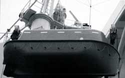
Figure 1. View of davit, showing lifeboat in the stowed and swung-out positions 1. Winch-brake remote-release cable, 2. Sheave, 3. Horn on davit, 4. Floating block, 5. Davit, 6. Suspension ring, 7. Bollard on lifeboat, 8. Gripe, 9. Falls, 10. Winch-brake handle, 11. Winch drum, 12. Davit hinge.
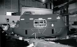
Figure 2. View of davits and side of lifeboat in the stowed position 1. Winch drum, 2. Electric motor, 3. Falls, 4. Sheaves, 5. Entrance hatch, 6. Harbour pins, 7. Lifeboat, 8. Davit head, 9. Winch-brake remote-release cable, 10. Forward horizontal bollard, 11. Embarkation platform, 12. Davit, 13. Davit hinge, 14. Skid.
The internal layout and configuration are typical of most modern, totally enclosed lifeboats. Seating is arranged fore and aft on either side and along the centreline. Crew members sit facing each other and secure themselves by wearing safety harnesses and seatbelts. The coxswain's seat is at the stern. It is raised to permit all-round vision from a conning tower built into the after, top portion of the canopy. All of the lifeboat's controls - the steering wheel, engine throttle, clutch, and winch-brake remote-release cable (see Figure 2, Item 9) - are accessible from this position, as is the central hook release handle (Photograph 12). This lever is fitted to the after bulkhead of the canopy and is situated aft and to port of the coxswain's seat.
Each lifeboat is powered by an inboard diesel engine that drives a fixed-pitch propeller. Steering is by means of a controllable Kort nozzle.
1.1.3 Davits, Winch, and Support Structure
The ship has two sets of steel davits - one on each side - on the first accommodation deck above the main weather deck. The davits form part of a steel cradle and framework that is welded to the deck. The davits are of the luffing type: they swing out by gravity and pivot on a hinged pin. In the stowed position, two harbour pins (cradle clamps) prevent the davits from accidentally swinging out.
At the top of the davit support frame is an embarkation and disembarkation platform at the level of the lifeboat side access hatch. The lifeboats are stowed inboard of the ship's sides. In the stowed position, the weight of the lifeboat is taken up by two horns: one forward and one aft. One end of each horn is welded to the davit; the free end passes through an eye in the floating block of the falls (see Photograph 4).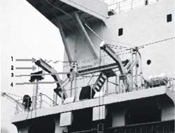
An electric winch is bolted to the after support frame. The winch carries two drums around which the continuous-wire falls wind. Via a system of sheaves and pulleys, the falls pass through two floating blocks to which two suspension rings are shackled. Each lifeboat has two permanently attached lifting hooks, one at each end. The hooks pass through these suspension rings, thus attaching the lifeboat to the falls.
The electric winch has a unidirectional freewheeling clutch and a brake that is activated by a weighted dead man's handle. This handle is also connected to the winch-brake remote-release cable (see Figure 2, Item 9), which passes through another set of sheaves and into the conning tower of the lifeboat, ending within easy reach of the coxswain.
The lifeboat is not designed to be bowsed alongside and is not equipped with bowsing tackle or tricing pendants.
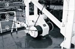
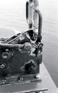
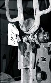
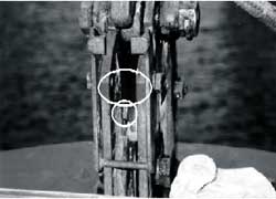
Photo 6. After view of lifeboat, showing davit, gripe arrangement around bollards, suspension ring, hook, and hatch
1.1.4 Bollards and Gripes
Two horizontal bollards are fixed to the lifeboat's hull, one at each end of the lifeboat. Circular guard plates are welded to the ends of the bollards. The base plate of the after bollard is flat and is inwardly inclined at 2° to the vertical; the base plate of the forward bollard is radiused and inwardly inclined at 7.5° to the vertical.
Steel wire rope gripes pass over these bollards. Each 14 mm-diameter gripe has a breaking strain of 13 000 kg - a load far exceeding the total weight of the lifeboat and its contents. The gripe is intended to hold the lifeboat hard-up against the davit frame and to prevent the lifeboat from hitting the frame in a seaway.
One end of each gripe is secured to a pad eye that is welded to the ship's deck; the other end passes over a freely rotating hooked lever that is attached to the side of the davit.
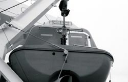
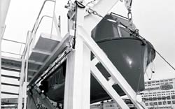
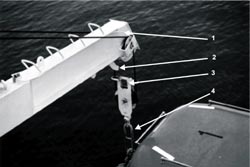
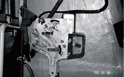
Photo 8. Forward view of lifeboat, showing davit, gripe arrangement around bollards, suspension ring, hook and hatch
In the lifeboat's stowed position, the free end of this rotating lever bears against the rigid support frame of the davit, preventing it from turning.
1.1.5 Lifting Hooks and their Release Mechanism
The lifting hooks are of the on-load/off-load release type. They are designed so that they can be opened simultaneously to release the lifeboat, either when it is out of the water and its weight is suspended from the falls or when the lifeboat is floating on the water and there is no weight on the falls.
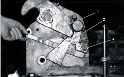
The hook assembly consists of the two side cheek plates, which form the frame to which attach the hook, the blocking lever, the reset lever, and the retaining latch (see Figure 6). These components all have holes drilled through them and are connected to the cheek plates via small shafts that pass through the components and the corresponding holes in the cheek plates. In the assembled arrangement, the parts are free to individually rotate about their shafts. The entire assembly is made of galvanized mild steel.
In the load-bearing or reset condition of the hook assembly (see Photograph 10), the flat end of the hook bears against and transmits a load onto the blocking lever, which in turn rests against a cam profile on the reset lever. At its contact surface with the hook, the blocking lever has a relief angle of 18°. As long as the reset lever remains in a position where its cam prevents the blocking lever from rotating downward, the hook remains locked and can carry its portion of the designed weight of the lifeboat and its contents (see Photograph 10).
At its free end, the reset lever carries a clevis joint to which is attached a teleflex cable. The other end of this cable is similarly fixed to a cable connection arm which, in turn, is fitted inside the central release control assembly (see Figure 3).
The functioning parts of the forward and after hooks are identical. Both hooks are mounted on the lifeboat in such a way that their orientation is in the same direction, facing aft.
On each hook assembly, the hook, the blocking lever, and the reset lever carry reference marks. The cheek plates have corresponding reference marks. The hook has been correctly reset when these marks are properly aligned.
The TSB's post-occurrence inspection of the hook assemblies indicated that, in the reset position, the reference marks on the reset levers were not aligned with the reference marks on the cheek plates. The top surface of the mark on the reset lever was just below the bottom surface of the marks on the cheek plates (see Photograph 20).
Hooks, designed to take a safe working load of 2.5 tons, have a minimum distance of 122.0 mm between the end of the load-transmitting surfaces and the circumference of their pivots. Once this dimension has been reached, the manufacturer recommends that the hook, the blocking lever, and the frame be renewed. On the forward hook of the lifeboat, this dimension was found to be within specification at 122.6 mm. However, on the after hook it was found to be 121.8 mm on average (see Figure 7). The retaining latch is designed to pivot such that it can only open into the hook (see Figure 6). This design feature allows the suspension ring to be inserted into the hook assembly and prevents the ring from inadvertently slipping out. The retaining latch is not designed to carry any significant amount of weight.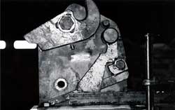
1.1.6 Central Release Control Assembly
The central release control assembly is just behind and to port of the coxswain's seat (see Photograph 12). It is made of two galvanized steel side plates to which are connected the release lever, the cable connection arms, and the interlock lever. A solenoid coil is mounted on top of the framework formed by the side plates.
The release lever is essentially a bell crank lever. One end of the lever forms the actual release handle; the other (free) end has two pins attached to it at right angles to its plane. These pins bear against the cable connection arms, which are connected to and rotate about the same shaft as the release lever. Pulling on the release handle allows these pins to lift the cable connection arms. The free movement of the release handle can be blocked by a safety pin, which is hinged at a point on one side plate and fits in a slot on the other side plate.
The interlock lever, also shaped like a bell crank, turns about its own shaft but in the same plane as the release lever and the cable connection arms. A mechanical linkage connects the interlock to a solenoid coil above it; a return spring is connected to the interlock lever from underneath. The interlock lever can swing into, or out of, a position where it blocks the upward travel of the cable connection arms and, thereby, the release handle. The free end of the interlock lever is enclosed in a housing, one side of which is covered by a clear Perspex removable window that faces the operator. In an emergency, the operator can remove the window and manually lift the interlock lever away from its blocking position. According to the instruction manual, the frame around the perspex window is painted in two colours: the top half is red and the bottom part green. When inspected by the TSB, the entire frame was found to be painted red.
The two cable connection arms are connected to reset levers on the forward and after hook assemblies via teleflex cables in such a way that they form an inflexible structure. When the cable connection arms move upward, under the action of the release handle, the reset levers are forced to move downward.
The central release control assembly houses three microswitches: two make contact with the two cable connection arms; the third is beneath the interlock lever with which it makes contact. The microswitches are used to indicate various operating conditions at the electrical alarm and control panel (see Section 1.1.8).
1.1.7 Water-Pressure Switch. (Hydrostatic Interlock.)
A pressure switch is fitted on the keel of the lifeboat. This switch senses whether the lifeboat is in or out of the water and transmits a corresponding electrical signal to the solenoid coil fitted over the interlock lever. Essentially, this switch consists of a diaphragm that flexes under the influence of hydrostatic pressure and thereby makes or breaks an electric contact, which in turn energizes or de-energizes the solenoid. The chamber above the diaphragm is maintained at atmospheric pressure by means of an equalising vent connection.
1.1.8 Pressure Switch and Alarm Light Control Box (Indication Panel)
Inside the lifeboat is an alarm light control box (see Photograph 13). The front panel of this control box has an on/off power supply switch and two indicating lamps: one red and one green. These lamps are connected to the three microswitches in the central release control assembly and to the water-pressure switch. The red lamp indicates two operating conditions: one when the lifeboat is out of the water and it is not safe to pull the release handle; the other when the hooks have been opened and the suspension rings released. The green lamp also indicates two operating conditions: one when the lifeboat is in the water and it is safe to pull the release handle; the other when the hooks have been correctly reset to the load-bearing position.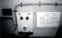
1.1.9 Description of a Typical Lifeboat Launch and Recovery
To launch a lifeboat, the harbour pins are first removed. This effectively removes all mechanical restraints on the davits, which are now held in position by the tension in the falls as they are turned up on the winch drum, which is held fast by its brake. The next step is to remove the stopper pin above the dead man's handle, which is connected to the winch brake. When the handle is lifted up, it disengages the brake, thus allowing the winch drum to rotate and the falls to pay out.
The davits turn about their hinge pins. As the davits move away from their support frames, the hooked levers (see Photograph 7) rotate and release the free ends of the gripes, which then fall away. The davits continue moving outboard of the ship, and the lifeboat swings out until it is clear of the ship's side. The floating blocks come free of the horns on the davits, and the full weight of the lifeboat is transferred to the falls. The stops on the davit frames halt further outward movement of the davits, and the lifeboat continues its descent into the water, suspended from the falls.
Once the lifeboat is floating on the water, the hooks are opened from inside the lifeboat by pulling on the central release handle. The suspension rings are now freed from the hooks, and the lifeboat can move away from the ship.
To reconnect the lifeboat to the falls, the forward and after hooks first have to be reset. The lifeboat is then manoeuvred and brought under the floating blocks, and the suspension rings are slipped into the hooks. The retaining latch prevents the suspension ring from slipping out when there is no load on the falls.
An electric winch hoists the lifeboat back up, until the floating blocks bear against the davit heads. As the winch continues to haul in the falls, the davit arms are forced to come off their stops and move inboard. This change in their angular disposition allows the davit horns to re-enter the floating blocks and also allows the lifeboat to move towards, and back into, its stowage position. The davits and the lifeboat are then secured by re-engaging the harbour pins and reconnecting the gripes. Slackening off the tension in the falls now has the effect of lowering the floating blocks until the weight of the lifeboat is transferred to the davit horns.
1.1.10 Procedure for Resetting the Hooks
The central release handle is first returned to its original (reset) position. The handle's bell crank lever thus moves away from the cable connection arms, allowing them to be pulled down when the reset levers are pushed up.
Each hook is turned until the red line painted on its side lines up with the cheek plate. The hook is held in this position with the right hand, while the left hand turns the blocking knob anticlockwise, until the reference arrow attached to it comes into alignment with a corresponding arrow on the cheek plate. The blocking knob is now held fast by the left hand, and the right hand pulls up the cable reset lever until it lines up with its own reference marks on the cheek plates. Once this has been done correctly, the safety pin in the central release control assembly is inserted into its slot and the release handle locked.
1.1.11 Lifejackets, Seats, and Seatbelts in the Lifeboats
The lifejackets complied with SOLAS requirements. In accordance with the relevant SOLAS regulations, the lifeboat was fitted with safety seatbelts at each seating position.
The following items of note were found on the Pacmonarch's two lifeboats:
- Many of the nuts securing the seatbelts to the shell were very loose on the port and starboard lifeboats.
- With the exception of a foam headrest, the seating area has no protective padding. Although the lifeboat had been designed for a free fall from a height of 3 m, no measure had been taken to soften the effect of the impact on the occupants of the lifeboat.
- A crew member wearing the supplied lifejacket would have had about 105 mm of hard flotation material (designed to support the wearer's neck in the water) protruding behind his/her neck. When seated at a designated seating area along the sides of the lifeboat, s/he would have another 55 mm of foam headrest, as well as the inwardly sloping roof of the lifeboat, bearing against this portion of the lifejacket and pushing his/her neck forward.
1.1.12 Operating Instructions and Training Requirements for the Lifeboat
The operations manual, which is written in English, describes in detail the procedures to release the hooks and to reset them before recovery of the lifeboat. The steps required to release the hooks are also set out on a placard mounted inside the lifeboat, beside the indication panel. These steps are written in English, in the form of a flowchart showing on-load and off-load release procedures. Information on the resetting procedure is not posted inside the lifeboat. A diagram of the three indicators (cable reset lever, hook position, and blocking knob), used while resetting the hooks, is also inside the lifeboat on the bulkhead adjacent to the forward and after hatches. However, the diagram has no text to indicate the correct procedures to follow.
The language of the crew was Ukranian, and not many of them were familiar with English. Both the captain and the chief officer spoke and understood written English.
The ship had in place a safety management system. Accordingly, both lifeboats had been launched three or four times since the delivery of the Pacmonarch. The crew had also conducted periodic lifeboat drills and was sufficiently trained in the procedures for launching the lifeboat.
1.2 History of the Voyage
The vessel was built in Sasebo, Japan, and delivered to its owners in July 2000. After making two voyages to Australia, the Pacmonarch sailed on a ballast voyage to Vancouver, British Columbia, arriving at about 0300Footnote 2 on 19 October 2000. It anchored at English Bay anchorage, waiting at a berth to load a cargo of grain.
During this period at anchor, the vessel's crew used the two lifeboats for trips ashore and to another vessel anchored nearby. The port lifeboat was used on October 24 without incident.
At about 1045 on October 26, the crew of the Pacmonarch started to launch the port lifeboat for an ordinary run ashore. The second officer, accompanied by the third assistant engineer and two seamen, boarded the lifeboat and prepared it from the inside, while the chief officer and another seaman removed the external securing arrangements. The plan was to lower the lifeboat to the lifeboat deck, where the rest of the shore party would board it. The lifeboat is designed to be boarded from the embarkation platform and is not equipped with bowsing gear to pull it alongside the ship. However, when lowered to a level where the side hatch is nearly flush with the lifeboat deck, it can also be boarded from this location.
The chief officer and the second officer were using handheld radio sets to communicate. The second officer sat in the coxswain's seat in the lifeboat's conning tower; the engineer sat behind him on the outboard (port) side of the lifeboat. A seaman was positioned at the forward hatch and another at the after hatch, near the hooks. The lifeboat's occupants all wore buoyant work vests and hard hats but did not attach their seatbelts, nor were they required to.
The second officer informed the chief officer that pre-launch checks had been carried out and that everything was in order. At this time, the chief officer was standing on the embarkation platform and facing the lifeboat. The seaman on the lifeboat deck was standing at the bow of the lifeboat.
Upon receiving the chief officer's permission to lower the lifeboat, the second officer pulled the winch-brake remote-release cable to disengage the winch brake. The davits turned out smoothly and the lifeboat swung to the ship's side easily and without jerking.
During the launch sequence and soon after the davits hit their stops, when the lifeboat was about 1.5 to 2.0 m below the davit head, the lifeboat became inclined, bow down, at about 40° to the horizontal. The after suspension ring then separated from its hook, damaging the retaining latch. The lifeboat then swung about the forward hook, which opened and released the forward suspension ring. Completely free, the lifeboat plummeted stern first into the sea.
The lifeboat became almost vertical (without ever actually going past vertical) before it hit the water. The impact considerably damaged the stern of the canopy. The hatches were open and water flooded into the lifeboat. As a result, the lifeboat lost its self-righting ability and floated with its starboard side submerged.
The master, upon hearing of the accident, rushed to the vessel's bridge and broadcast a "Mayday". A tug and a water taxi were attending a ship at an adjacent anchorage. Hearing the broadcast, they rushed to the rescue and arrived on the scene first. The seaman, stationed by the forward hatch, had managed to crawl back to it. He was seen by the crew and lifted out to safety.
There was an experienced diver on board one of the boats and, though unequipped with proper diving gear, he nevertheless entered the lifeboat to try and extricate the others. He found them unconscious, surrounded by the debris of the boat's fall and lying in the water that was entering the boat. The diver managed to reach one of the crew and, assisted by other rescuers, pulled him out.
By this time, a Canadian Coast Guard rescue vessel had reached the scene. Its diving team started cutting the partially broken stern section of the canopy to increase the opening. They were thus able to remove the lifeboat's remaining two occupants. Although the Coast Guard administered first aid and rushed the victims to hospital for treatment, three of the four men on board the lifeboat did not recover consciousness and succumbed to their injuries.
Because of concern that the lifeboat might sink, attempts were made to reattach the hooks to the falls and to lift it clear of the water. These attempts were unsuccessful and the lifeboat was towed to the Kitsilano Coast Guard base.
1.3 Description of a Similar Accident
On 06 August 2000, the crew of the Washington Trader, a sister vessel of the Pacmonarch, was carrying out a training launch of its port lifeboat at Abbot Point, Queensland, Australia. In very similar circumstances, the lifeboat separated from its after falls and swung about the forward hook, which also opened. The lifeboat then fell stern first into the sea.
The damage to the two lifeboats was almost identical, including the damage to the retaining latch on the after hook. Because no one was in the Washington Trader's lifeboat and there was no urgent need to rescue trapped people, the master of the vessel was able to preserve the lifeboat as is.
Investigators of the Australian Transport Safety Bureau found the after hook to be in the closed or reset condition and the forward hook to be open.Footnote 3
1.4 Injuries to Persons
| Crew | Passengers | Others | Total | |
|---|---|---|---|---|
| Fatal | 3 | - | - | 3 |
| Missing | - | - | - | - |
| Serious | - | - | - | - |
| Minor/None | 1 | - | - | 1 |
| Total | 4 | - | - | 4 |
1.5 Damage
1.5.1 Damage to the Lifeboat
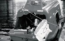
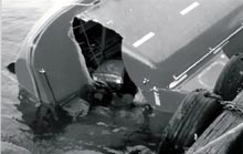
The impact with the water caused considerable damage to the stern of the lifeboat, with most of the damage concentrated around the canopy. The vertical panel was pushed inward, and the glass-reinforced plastic was torn right through. During rescue operations, divers further cut this torn opening and folded back the entire vertical panel, giving them unhindered access to the inside of the lifeboat (see Photograph 14, 15).
Inside the lifeboat, the coxswain's chair and the frame of the central release control assembly were attached to the after bulkhead. The chair's support frame was badly buckled and broken and the control assembly frame's brackets were found to be completely broken off. The horizontal part of the canopy (onto which the after hook assembly, the towing bracket, and the other attachments were fixed) was bent upward. Portions of the canopy were torn and bolts securing the canopy to the hull were also broken. Other internal damage consisted of bent rudder linkages, holding-down brackets, and holding-down frames.
1.5.2 Damage to Hook Assemblies and Suspension Rings
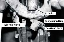
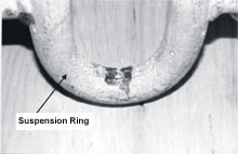
The retaining latch on the after hook assembly was damaged in such a way that its two vertical forked arms were both bent sideways and outboard of the lifeboat (see Photograph 16). The after hook was not damaged, but had scoring marks on its inside surface in the area that comes .in contact with the suspension ring. The after suspension ring was not damaged but did have two small scoring marks on the outside bottom surface in an area that comes in line with the forked arms of the retaining latch (see Photograph 17).
The forward hook assembly and its suspension ring were not damaged.
1.5.3 Damage to Davits, Winch, Frames, Floating Blocks, and Falls
The davits, davit winch, and davit frames were not damaged; neither were the floating blocks or the falls. Paint at the joint between the winch foundation plate and the frame was found chipped and broken. The rest of the paint was intact.
1.6 Certification
1.6.1 Vessel
The Pacmonarch was certificated according to the requirements for a vessel of its class and type. The certificates were all valid and current.
1.6.2 Personnel
The officers and the crew on board were properly certificated and met the requirements of the International Convention on Standards of Training, Certification and Watchkeeping for Seafarers, 1995.
1.7 Testing of the Starboard Lifeboat
The day after the accident, and on subsequent dates, the starboard lifeboat was launched several times. The launchings were videotaped, and the tape later analyzed. At each launching, the forward and after gripes fell free of the davit, but turned up on and temporarily became fouled on the lifeboat's bollards before the floating block cleared the horns on the davits.
2.0 Analysis
The requirements outlined in International Convention for the Safety of Life at Sea, 1974 (SOLAS) for the design of lifeboats and lifeboat release mechanisms focus primarily on the engineering design requirements for safe operation.Footnote 4 The Pacmonarch's lifeboat fully complied with all SOLAS requirements. A human factors or ergonomic analysis could identify design deficiencies that, instead of being based on engineering principles, are based on how the design influences the effectiveness, efficiency, and safety of seafarers using this type of evacuation system.
When considered in isolation, a design aspect may not contain a serious deficiency. However, when all the lifeboat's components are integrated and considered as a whole, they present a risk whereby the lifeboat may be raised or lowered with the hooks improperly reset and the interlock not engaged. This condition could, and did, result in the lifeboat's accidental release and the consequent injury, loss of life, and damage to property.
2.1 Hook Design and Orientation and Ergonomics of Hook Resetting
The forward and after hook assemblies both face aft so that the lifeboats can be lowered into the water while the ship is making headway. This could cause the lifeboat to be towed along by its falls, changing the relative angle between the falls and the hook. Orienting the hook openings in this way removes the possibility of the suspension rings slipping out of the hook. However, this arrangement also makes it difficult to see if the after hook has been properly reset.
Resetting the hooks is a three-part, two-handed process, in which the right hand has to perform two different actions. The right hand first has to hold down the hook, while the left hand turns the blocking knob to bring up the blocking lever. The right hand then has to release the hook, then reach down and pull the reset lever up to the reset position, so that the lever lines up with the corresponding reference marks.
In the forward hook assembly, the reset lever and the red painted reference marks on the cheek plates face into the lifeboat. This orientation makes it easy for the operator to check whether the hook has been correctly reset.
In the after hook assembly, the reset lever and the reference marks face aft and away from the operator. This orientation requires the operator to lean half outside the small hatch and to twist around to view the alignment of the reference marks on the reset lever and the cheek plates. This process is awkward, especially since the operator is wearing a bulky lifejacket and a hard hat and if the lifeboat is moving in a seaway. This difficulty reduces the likelihood of the visual check being performed. Additionally, once the operator has visually checked for the correct resetting and has re-entered the lifeboat, s/he is unable to continuously verify that the reset lever has remained in place and has not slipped down. With the forward hook, the check can easily be done at any time. With the after hook, the check can only be done by repeating the procedure described above.
Because of the after hook's awkward orientation, the operator tends to use other sources of feedback that, although more readily available, are not reliable indicators of whether the reset lever is in the correct position. In particular, the red alignment line drawn on the side of the hook can be inappropriately used as the main indicator. Thus, the operator looks to see that this red line is aligned and that the hook stays up and feels secure when shaken. The operator then assumes that the mechanism is fully reset and locked. The after hook's aft-facing orientation places its reset lever where the operator cannot easily manipulate it, verify that it has been correctly reset, or see that the lever has remained in place after being reset.
2.2 Interaction Between Gripes, Gripe Release Arrangement, and Lifeboat
The following was observed when videos of the test launching of the Pacmonarch's (and of its sister ship, the Pacemperor) starboard lifeboats were analyzed and reviewed in slow motion.
During the initial part of the launch sequence, the davit's luffing action toward the ship's side causes the lifeboat to swing outward. As the davit draws away from its support frame, it creates an ever increasing gap between itself and the rigid frame. This gap frees the rotating lever, to which the davit end of the gripe is hooked, and allows the lever to turn and release the gripe.
The lifeboat's outward motion creates tension in the gripes, which in turn creates angular velocity in the free end of the gripe. The free end of the gripe falls, causing the gripe to loop around the bollard on the lifeboat and, as the relative distance between the free end of the gripe and the bollard reduces, the angular velocity of the free end increases.
By the time the davits have reached an angle of about 60°, the end of the gripe has gained so much velocity that the gripe wraps itself around the bollard. Since the other end of the gripe is fixed to the deck, the gripe is forced to immediately and violently unwrap itself as the lifeboat continues its swing and the distance between it and the davit frame increases. The gripe's turn around the bollard reduces in diameter and eventually coils around it. At this point, the ring on the free end of the gripe has reached the bollard, and the entire gripe is looped around it.
On the day of the occurrence, it is most likely that the end of the after gripe fouled and seized around its bollard as the port lifeboat was lowered. Consequently, the lifeboat took a bow-down attitude, the load partially transferred from the after falls to the gripe, and the after hook separated from its suspension ring.
2.3 Dynamics of the Accidental Separation of the After Hook
The entire process of the gripe turning itself up around the bollard takes about two seconds; a complete wrapping and unwrapping takes about four seconds. The precise dynamic behaviour of the gripe is unpredictable and a function of the initial pre-tension in the gripe, the smoothness with which the winch brake is lifted and the lifeboat is launched, the resistance offered by the davits in their hinges, the resistance offered by the rotating lever, the friction between the horns on the davits and the floating blocks, the trim and list of the ship, etc.
When the gripe wraps itself tightly around the bollard, the ring at the gripe's end sometimes gets caught between the gripe and the side of the lifeboat. Since the base plate of the after bollard is flat and lies on the flat, vertical stern of the lifeboat, the after gripe end is much more likely to foul in this way than the gripe on the forward bollard, the base of which is radiused backwards to conform to the shape of the lifeboat's bow.
Because the gripe is of fixed length and the lifeboat was being lowered away, part of the load from the after falls momentarily transferred to the fouled gripe. The rate of descent of the lifeboat's after end decreased momentarily, but since the falls were still being paid out, the lifeboat's forward end became lower than its after end. The restraint on the after end, caused by the fouled gripe, also held the after end "in", closer to the ship side than the forward end.
The lifeboat at this point was bow down around 40° (as suggested by matching the witness marks on the damage to the after hook and its suspension ring) when the gripe freed itself and detached from the after bollard. At this angle, the after suspension ring bore against the tip of the hook, and the retaining latch overcame the resistance offered by it and slipped out. Completely separated from the after falls, the lifeboat swung like a pendulum about the forward hook, which was still attached to the forward falls.
2.4 Analysis of the Hook Assembly
2.4.1 Hook Design
The reset lever holds the hook in a position where it can bear an applied load. However, this applied load creates turning moments on the hook and the blocking lever and also manifests itself as friction between the blocking and reset levers. The frictional force increases with increasing applied load and is mainly responsible for holding the reset lever in the reset position. If the applied load is removed, so also is the frictional force, and the reset lever is now held in position only by the friction in the teleflex cable and the linkages that connect the reset lever to the central release control assembly. These linkages are well lubricated, and their friction coefficient is low. An analysis of the moments due to the weights of the reset lever arm and the cable connection arm shows that the reset lever has the higher moment.Footnote 5
Once the suspension rings have been inserted into the hooks, and while the lifeboat itself is riding successive crests and troughs in the waves, this applied load becomes transient and associated with sudden changes in direction of momentum that would tend to allow the reset lever to fall in the opening direction. To prevent such an inadvertent or accidental opening of the hooks, the interlock lever in the central release control assembly has been designed to block the cable connection arms and hold them in position. The reset lever has no other means of ensuring that it stays in place.
The hook, the reset lever, and the blocking lever have been designed to rotate about pivots. To swing the blocking lever away and release the hook, the reset lever must first be moved out of the way. Since the reset lever moves in an arc, its contact surface with the blocking lever is also an arc. However, the corresponding contact surface of the blocking lever is planar, thus creating a line contact between these two surfaces (see Section 2.4.2). At its contact surface with the hook, the blocking lever has been given a relief angle of 18°. This angle also creates a line contact between them.
The retaining latch allows the suspension ring to be inserted into the hook. Because the latch can only open inward, it retains the ring within the hook assembly. To remove the suspension ring from a hook that has been locked by the blocking lever and the reset lever, the retaining latch has to be manually turned inward, creating an opening through which the ring can be slipped. The retaining latch is not designed to take any significant applied loads.
2.4.2 Forces Acting on the Reset Lever
The force exerted by the blocking lever on to the reset lever will pass through the centre of rotation of the reset lever, as long as the centre of rotation is in the same line as the centre of its radiused contact surface. If the two centres are not in the same straight line, the force will create a turning moment on the reset lever, tending to move it up or down.
The two hook assemblies were tested in a tensile testing machine. A uniformly increasing load was applied to the forward and after hooks at three angular positions of the reset lever (see Appendix A - Tables 1 and 2). When the reset lever was fully reset, the applied loads created a proportionate turning moment on the reset lever, which tended to move down (toward open). Other angular positions produced a negligible turning moment on the reset lever.
The turning moment detected on the hook reset lever indicates that the profile of the lever's load-bearing cam was not of a uniform radius, concentric with the centre of rotation. Because the equipment was new and wear was undetected and unlikely, this profile is a deviation from the designed profile and indicates a manufacturing nonconformity.
2.4.3 The Load-Transmitting Surfaces of the Hooks and their Manufacturing Nonconformities
Figure 7. The release hook, the frame, and the lever should be replaced when the wear at the contact point between the release hook and the frame reaches 122 mm for a 2.5-ton hook.
The load-transmitting contact surface on the hook wears with use, reducing the length from the end of its load-transmitting surface to the circumference of its pivot. According to the manufacturer, this minimum distance is 122.0 mm. A shorter length can lead to two effects, both potentially detrimental:
- The contact line between the hook and the blocking lever will shift away from the blocking lever. Since this face of the blocking lever has been given a relief angle of 18°, the hook could eventually slip past the blocking lever, rotate, and release the applied load.
Although this length on the after hook was found to be around 121.8 mm (0.2 mm below specification), the design had an adequate factor of safety, and there is no indication that this hook ever slipped past its blocking lever. However, the lifeboat and its hook assemblies were only about a year old, and the lifeboat itself had only been launched about four or five times. This use is not considered sufficient to have caused appreciable wear. - As the contact line between the hook and the blocking lever shifts away from the blocking lever, it also allows the hook to change its vertical angle, that is, to revert to its original position.
Minimal wear was found on this surface and the original radius was intact. The manufactured length from the end of the hook's load-transmitting surface to the circumference of its pivot was therefore 121.8 mm. Because the equipment was new and the wear minimal, this length is a deviation from the designed profile and indicates a manufacturing nonconformity.
2.4.4 Ergonomics of the Alignment Marks for the Reset Lever
When the hook is fully and properly reset, the red mark on the tip of the reset lever should line up with the corresponding red mark on the cheek plates of the hook assembly. This alignment provides visual feedback to the operator that the lever is in the correct position and confirms that the hook has been fully reset.
If the hook reset indicators are not aligned, the possibility of error exists, since the task now changes from one where a precise judgement is required (whether the red reference marks are aligned) to one where an imprecise judgement is required (whether the reference marks are "close enough"). Less precise specifications result in more subjective judgements and a greater risk of error.
Accurately aligned reference marks are an anchoring aid and prevent a drift in standards. Inaccurately aligned reference marks may lead future operators to accept increasing misalignments as the norm. The misaligned hook reset reference marks did not provide the crew with an accurate indication that the reset lever was in the fully up position and, critically, that the hook was properly reset.
2.5 Central Release Control Assembly
Pulling on the release handle moves the cable connection arms upward and pulls the reset levers downward. Teleflex cables connect the cable connection arms to the reset levers on the hook assemblies. As a result, the blocking lever rotates away from the hook, and the hook swings open and releases the suspension ring. The lifeboat is then no longer attached to the falls.
The release handle acts on the forward and after cable connection arms simultaneously. To accomplish this, the distance the reset levers have to be moved before releasing the blocking levers is adjusted at the initial setup.
The interlock lever prevents the cable connection arms from travelling upward after the hooks have been reset. This lever is mechanically connected to a solenoid coil that is activated by an electrical signal from a hydrostatic pressure switch. When the lifeboat is floating on the water, the solenoid coil moves the interlock away, allowing the operator to pull the release handle and open the hooks. This sequence is known as an off-load release.

In case the lowering mechanism malfunctions, which could cause the lifeboat to become suspended from the falls, the hooks are also designed for an on-load release. In this case, the Perspex window in front of the interlock lever's free end is broken, and the interlock is physically lifted off the cable connection arms. The operator can now pull on the release handle to release the hooks and allow the lifeboat to fall to the water.
Once the reset levers have been moved into their locking position, they have no intrinsic force to hold them in place. By restricting the movement of the cable connection arms, the interlock lever holds the reset levers up. The interlock lever also holds the hooks in a condition where they can take the applied load and prevents the hooks from accidentally or inadvertently opening.
It is therefore critical for the operator to know the position of the interlock lever in relation to the cable connection arms. The two side plates of the central release control assembly are made of galvanized mild steel in which there is no opening. Therefore, one cannot directly view the interface between the interlock and the cable connection arm. The free end of the interlock lever is housed in a frame, one side of which has a clear plastic window. However, there are no reference marks between this end of the lever and the frame to accurately indicate whether the other end of the interlock is in a blocking position.
The manufacturer's operations manual instructs the operator to check whether the free end of the interlock lever is up or down to determine its relative position. With no definitive mark to provide a point of reference, the operator's judgement of up or down becomes subjective and prone to error.
The assembly is mounted against the after bulkhead of the lifeboat. One can look into the gap between the two side plates of the assembly housing to get an indication of the position of the interlock lever. However, given the dim lighting inside the lifeboat and that the crew member is wearing a hard hat and a lifejacket, this operation is difficult and uncomfortable and also prone to parallax error.
Thus, although the manufacturer's instruction manual indicates the importance of verifying the position of the central release interlock lever, the design and placement of the central release control assembly makes this crucial task difficult.
2.6 The Indication Panel
The indication panel displays the status of the lifeboat by using red and green lamps. The panel indicates whether the lifeboat is floating on the water or is suspended in the air and whether it is safe to pull the release handle to open the hooks. Because the two indication panel lamps are multifunctional, each can indicate two separate and contrary operating conditions. In the absence of a straightforward means of seeing the interlock lever's position, the red and green lights are regarded as the most direct and accurate indication of the status of the hook release mechanism. It is essential that the feedback these lights provide be accurate.
The lamps' indications are dictated by the contacts made between the cable connection arms, the interlock lever, and their respective microswitches. The positioning of these microswitches (see Figure 4), and the excessive play found in their sensing arms, allowed the panel lamps to falsely indicate the position of the interlock lever. When one or both of the cable connection arms were not being blocked by the interlock lever, the panel lights could incorrectly indicate that they were blocked.
2.7 Typical Interaction Between the Hook Assembly, the Central Release Assembly, and the Indication Panel
Once the reset levers have been moved into the fully reset position, their corresponding cable connection arms contact the microswitches, and the green lamp on the panel lights up to indicate that the hooks have been correctly reset. If one or both of the reset levers are now moved down as much as 30 mm, the green lamp will continue to remain lit, thus indicating that the hooks are still reset properly.
At some point during the recovery of a lifeboat (when the lifeboat is in the water and the forward and after hooks have been reset correctly), one or both of the suspension rings are inserted into the hooks and the lifeboat rides the waves. While the lifeboat is in the water, the solenoid coil connected to the interlock lever is energized and does not allow the interlock lever to block the cable connection arm.
During this same time, the movement of the lifeboat on the waves produces an intermittently applied load on the hook. This load can move the hook release handle down (toward open). This movement, coupled with the associated change in direction of momentum, can allow the reset lever to fall slightly. Its cable connection arm is now lifted and can no longer be blocked by the interlock lever when the lever is released by the solenoid coil.
Malfunctioning or 'sticky' electrical contacts in the indication panel or the water pressure switch can also cause the solenoid coil to become energised. These were all tested and found to be working satisfactorily.
2.8 Dynamics of the Accidental Release of the Forward Hook
When the reset lever is in its fully reset position, it is 12 mm lower than its maximum attainable position. Because the lever's reference marks were never in alignment in the first place, the drop of the reset lever goes unnoticed. Moreover, only the reset lever on the forward hook is readily visible. Static load testing of the hook assemblyFootnote 6 shows that, in this condition, the hook remains fully capable of bearing the applied load of the lifeboat and its contents.
However, because the interlock lever is no longer blocking the cable connection arm, the reset lever is now vulnerable to the influence of forces tending to move it downward (open). These forces become predominant when the direction of momentum changes and when the applied load increases. The forces can then cause the reset lever to move down (open). The hook would now open and the suspension ring would be released - just as if the central release handle was pulled.
Following the accidental separation of the after hook, the forward reset lever moved unimpeded into the open position because of the increased momentum and load applied at the forward hook when the lifeboat swung about it. The forward suspension ring was thereby released.
2.9 Lifeboat Construction
Both of the Pacmonarch's lifeboats complied with all the SOLAS requirements and offered an urgent means of escape for the ship's crew. Nonetheless, a lifeboat may also be required to recover persons in the water. In agitated and confused seas, an "unhandy" craft, such as a covered lifeboat, is difficult to manoeuvre. Because survivors are normally recovered on the lee side, the provision of access hatches on both sides of the canopy could reduce the time needed to manoeuvre the lifeboat into a position to recover persons in the water and could increase their chance of survival.
2.10 Lifejackets, Seats, and Seatbelts in the Lifeboats
The lifeboat was designed for free fall from a height of 3 m. Yet when TSB investigators sat in the lifeboat and simulated a fall from about 0.5 m, the jar to the spine was considerable when the lifeboat hit the water.
The combination of the slope of the lifeboat's canopy, the protrusion of the lifejacket behind the wearers' necks, and the padded headrests forced the wearers to bend their necks forward at a very awkward angle. TSB investigators sat this way for about 30 minutes and found it to be quite uncomfortable and painful. Given the cramped quarters and the lack of free space inside the lifeboat, removing the lifejackets and stowing them away would not be easy.
People abandoning a vessel may have to spend a considerable length of time in such a vessel, in all kinds of weather. It is difficult to envisage how they could avoid neck injuries while wearing standard lifejackets and bracing themselves against the lifeboat's rolling and pitching. The design of the lifeboat and, in particular, its seating did not make allowance for the fact that the occupants would be wearing standard lifejackets. The lifeboat's uncushioned seating arrangements, combined with the limited headroom when seated and the effect of wearing standard lifejackets, is not conducive to crew comfort and could lead to crew injury. Further, the lifeboat seatbelts are not long enough to efficiently secure a large person to the designated seating when wearing a standard lifejacket.
2.11 Operating Instructions and Training Requirements for the Lifeboat
SOLAS regulations address a number of training considerations, including muster lists, emergency instructions, training manuals, and abandon-ship training and drills. This shipboard training helps ensure that the crew will be able to abandon ship successfully in an emergency. Less emphasis is placed on training the crew in lifeboat recovery procedures, presumably because the recovery of the lifeboat is not the primary consideration once the crew has abandoned the vessel.
Although all the instruction manuals were written in English, the Ukranian crew of the Pacmonarch had regularly and successfully conducted abandon-ship drills since the vessel was delivered in July. By virtue of this and other continuous proficiency training, before and during their seafaring career, the crew was well versed in launching the lifeboats. The procedure for resetting the hooks, however, was not as well understood by the whole crew. Given the crucial importance of the resetting operation, the availability of an aide-memoire in the lifeboat could have improved the likelihood of the hooks being correctly reset. The instruction manual describes in detail the correct hook-resetting procedure, but this information is not posted inside the lifeboat in written or graphic form for the crew's use.
3.0 Findings
3.1 Findings as to causes and contributing factors
- When the davits swung out as the lifeboat was lowered, the end of the after gripe probably fouled and seized around its bollard.
- Temporarily "hung up" on the after gripe, the lifeboat then took a bow-down attitude of about 40°, and the after suspension ring moved toward the hook opening.
- When the gripe freed itself and the load returned to the after falls, the loading most likely caused the after suspension ring to overcome the resistance of the retaining latch and to slip out of the hook.
- Following the accidental separation of the after hook, the forward reset lever moved unimpeded into the open position because of the increased momentum and load applied at the forward hook when the lifeboat swung about it. The forward suspension ring was thereby released.
3.2 Findings as to risk
- Although the instruction manual describes in detail the correct hook-resetting procedure, this information is not posted inside the lifeboat in written or graphic form for the crew's use.
- The after hook's aft-facing orientation places its reset lever where the operator cannot easily manipulate it or see that the lever has remained in place after being reset.
- The misaligned hook reset reference marks did not provide the crew with an accurate indication that the reset lever was in the fully up position and, critically, that the hooks were properly reset.
- The manufacturer's operations manual instructs the operator to check whether the free end of the central release interlock lever is up or down to determine its relative position. With no definitive mark to provide a point of reference, an operator's judgement of up or down becomes subjective and prone to error.
- Although the manufacturer's instruction manual indicates the importance of verifying the position of the central release interlock lever, the design and placement of the central release assembly makes this crucial task difficult.
- Because the two indication panel lamps are multifunctional, each can indicate two separate and contrary operating conditions.
- When one or both of the cable connection arms were not being blocked by the interlock lever, the indication panel lights could incorrectly indicate that they were blocked.
- The manufactured length from the end of the after hook's load-transmitting surface to the circumference of its pivot was 121.8 mm. Because the equipment was new and the wear minimal, this length is a deviation from the designed profile and indicates a manufacturing nonconformity.
- The turning moment on the hook reset lever indicates that the profile of the lever's load-bearing cam was not of a uniform radius, concentric with the centre of rotation. Because the equipment was new and wear was undetected and unlikely, this profile is a deviation from the designed profile and indicates a manufacturing nonconformity.
- During recovery of the lifeboat from the water, the movement of the lifeboat on the waves produces an intermittently applied load on the hook. This load can move the hook release handle down (toward open).
3.3 Other Findings
- The design of the lifeboat and, in particular, its seating did not make allowance for the fact that the occupants would be wearing standard lifejackets.
- The design of the lifeboat's uncushioned seating arrangements, combined with the limited headroom when seated and the effect of wearing standard lifejackets, is not conducive to crew comfort and could lead to crew injury.
- The lifeboat seatbelts are not long enough to efficiently secure a large person to the designated seating when wearing a standard lifejacket.
- The provision of access hatches on both sides of the lifeboat canopy could reduce the time to manoeuvre the lifeboat into a position to recover persons in the water and could increase their chance of survival.
- Although the lifeboat was designed for free fall from a height of 3 m, a simulated fall during testing from about 0.5 m caused considerable jarring and discomfort to the occupants when the lifeboat hit the water.
4.0 Safety Action
4.1 Action Taken
The TSB sent a Marine Safety Advisory (MSA 05/01) to the Bahamas Maritime Authority, with a copy to the vessel owner, and a Marine Safety Information Letter (MSI 02/01) to the International Association of Classification Societies, the Bahamian flag state, Transport Canada, Class NK, the owners of the Pacmonarch, the manufacturers of the lifeboat and davits, and the ship builder, to advise them of the ergonomic and design deficiencies of the hook and central release control assemblies. The MSI also stressed the importance of ensuring that the interlock lever blocks the cable connection arms.
In response, Transport Canada Marine Safety (TCMS) issued Port State Control Instruction No 3, based on this and other similar accidents, concerning the premature release of lifeboat safety hooks. Inspectors are referred to Ship Safety Bulletin 05/2000 and other documents to ensure that, during inspections, all launching systems are inspected and that the crew is familiar with the correct sequences for launching and retrieving survival craft. If deficiencies are detected, the vessel is to be detained.
TCMS also advised that Australia, Canada, and New Zealand submitted a joint paper (DE 45/17) to the International Maritime Organization's Subcommittee on Ship Design and Equipment, on 14 December 2001, to raise awareness of the safety issues surrounding the operation and maintenance of totally enclosed lifeboats. The paper was intended to assist the subcommittee in its consideration of accident prevention and set out various possible short, medium and long term measures.
Three tanker operator organizations (OCIMF, INTERTANKO & SIGTTO), in supporting these papers, submitted further information to the subcommittee on 25 January 2002. This information included additional items about lifeboat design, operations, standards, guidelines, training, and maintenance aspects for consideration in the short and medium terms. The subcommittee met in March 2002 and will next meet in 2003.
The TSB convened a meeting at its Engineering Laboratory facility in April 2001. Representatives of the lifeboat, davit, and ship manufacturers, the vessel's owner, and the lifeboat manufacturer's sales agent attended. Deficiencies noted in the design of the hook and release mechanisms were discussed and demonstrated. The discussion was thorough and constructive, and particular emphasis was placed on the design of the user-machine interface.
After the meeting, Lasco Shipping Co., the operating managers of the vessel, decided to replace all four lifeboats on the Pacmonarch and the Pacemperor with lifeboats of another design made by a different manufacturer.
The lifeboat manufacturer, Nishi-F Co. Ltd., responded to the MSI with more information regarding the reset position and process for the hooks, the system of lights and the interlocks.
After an investigation, the Bahamas Maritime Authority has recommended that the classification society, Class NK, reconsider approval of this type of lifeboat until the manufacturers make changes in accordance with its recommendations. These apply to all lifeboats, both existing and new, and are, inter alia:
- Manufacturers to consider making a viewing port on the side of the central release assembly, to allow a direct view that the interlock lever is actually blocking the cable connection arm, when the hook mechanism has been reset.
- Manufacturers to consider fitting the aft hook with the open end facing forward, so that the red alignment marks are easily viewed when being reset by the lifeboat crew.
- Verify that the red alignment marks align correctly before delivery.
The Japan Classification Society, Class NK, responded to the MSI, advising that some 340 boats, manufactured by Nishi-F Co. Ltd., had been installed on ships using their services since 1987. Class NK sent an advisory note to all their offices and to all known owners of vessels with this type of lifeboat.
Class NK has had discussions with the lifeboat manufacturer, as a result of which they have decided to :
- cease all further production of this design of hook release mechanism;
- deliver safety bars to all other existing ships with lifeboats of this type. These safety bars will be inserted into the central release assembly, to prevent inadvertent, premature opening of the hooks;
- simplify their instruction and operation manual so that it can be more easily understood; and
- develop training videos for the operation and deployment of the lifeboat.
The International Association of Classification Societies (IACS) has circulated the information in the MSI to all their members who will consider what action is deemed necessary.
4.2 Safety Concern
Lifeboat Ergonomics
The advisory and information letters mentioned in Section 4.1 dealt with the practicalities of lifeboat safety hooks, their design and the ergonomics involved in releasing or re-attaching the blocks. It is acknowledged that officials and organizations have taken action and that the problems encountered have been brought to the attention of IMO.
However, the Board remains concerned that injury to crew may result during lifeboat drill or the abandonment of the vessel. Tests conducted by TSB personnel in the Pacmonarch's davit launched enclosed lifeboat indicated that the design of the lifeboat's seating arrangements did not allow crew, who were wearing standard lifejackets, to be safely seated. The lifeboat was designed to fall from a height of 3 m above the water but, during a test from about 0.5 m, the occupants suffered considerable jarring when the lifeboat hit the water. The uncushioned seating, limited headroom, too short seat belts and the seated position of a crew person wearing a standard lifejacket create the conditions which may, as a result of the boat being released, cause personal injury.
This report concludes the Transportation Safety Board's investigation into this occurrence. Consequently, the Board authorized the release of this report on .
Appendix A - Tables 1 and 2
Table 1
| FORWARD HOOK | |||||||
|---|---|---|---|---|---|---|---|
| Applied Load | Output (kg) | ||||||
| Lever Position: Fully Reset (0 mm) | Lever Position: As Rigged (20 mm) | Lever Position: Midtravel (50 mm) | |||||
| lbs | kg | Initial | Final | Initial | Final | Initial | Output |
| 0.0 | 0.0 | 3.0 | 3.0 | 0.4 | |||
| 250.0 | 113.4 | 6.4 | 3.0 | 0.5 | |||
| 500.0 | 226.8 | 10.0 | 3.0 | 0.5 | |||
| 750.0 | 340.2 | 13.5 | 3.0 | 0.5 | |||
| 1000.0 | 453.6 | 15.2 | 3.0 | 0.5 | |||
| 1250.0 | 567.0 | 17.1 | 3.0 | 0.5 | |||
| 1500.0 | 680.4 | 19.2 | 3.0 | 0.5 | |||
| 1750.0 | 793.8 | 20.8 | 3.0 | 0.5 | |||
| 2000.0 | 907.2 | 22.3 | 3.0 | 0.5 | |||
| 2250.0 | 1020.6 | 23.5 | 3.0 | 0.6 | |||
| 2500.0 | 1134.0 | 24.8 | 3.0 | 0.6 | |||
| 2750.0 | 1247.4 | 25.8 | 3.0 | 0.6 | |||
| 3000.0 | 1360.8 | 26.9 | 3.0 | 0.6 | |||
| 3250.0 | 1474.2 | 28.0 | 3.0 | 0.6 | |||
| 3500.0 | 1587.6 | 29.1 | 3.0 | 0.6 | |||
| 3750.0 | 1701.0 | 30.1 | 3.0 | 0.6 | |||
| 4000.0 | 1814.4 | 31.0 | 3.0 | 0.6 | |||
| 4250.0 | 1927.8 | 32.0 | 3.0 | 0.6 | |||
| 4500.0 | 2041.2 | 32.8 | 3.0 | 0.6 | |||
| 4750.0 | 2154.6 | 33.7 | 3.0 | 0.7 | |||
| 5000.0 | 2268.0 | 34.3 | 3.0 | 0.7 | |||
| 5250.0 | 2381.4 | 35.2 | 3.0 | 0.7 | |||
| 5500.0 | 2494.8 | 35.9 | 3.0 | 0.7 | |||
(Note: The applied load expressed in pounds is accurate. The conversion to kilograms is approximate.)
Table 2
| AFTER HOOK | |||||||
|---|---|---|---|---|---|---|---|
| Applied Load | Output (kg) | ||||||
| Lever Position: Fully Reset (0 mm) | Lever Position: As Rigged (20 mm) | Lever Position: Midtravel (50 mm) | |||||
| lbs | kg | Initial | Final | Initial | Final | Initial | Final |
| 0 | 0.0 | 3.0 | 3.0 | 0.6 | |||
| 250.0 | 113.4 | 3.4 | 3.0 | 0.7 | |||
| 500 | 226.8 | 5.1 | 3.0 | 0.7 | |||
| 750.0 | 340.2 | 6.4 | 3.0 | 0.7 | |||
| 1000 | 453.6 | 7.3 | 3.0 | 0.7 | |||
| 1250 | 567.0 | 7.9 | 3.0 | 0.7 | |||
| 1500 | 680.4 | 8.7 | 3.0 | 0.7 | |||
| 1750.0 | 793.8 | 9.5 | 3.0 | 0.7 | |||
| 2000 | 907.2 | 10.3 | 3.0 | 0.7 | |||
| 2250.0 | 1020.6 | 11.0 | 3.0 | 0.7 | |||
| 2500.0 | 1134.0 | 11.7 | 3.0 | 0.7 | |||
| 2750.0 | 1247.4 | 12.3 | 3.0 | 0.7 | |||
| 3000 | 1360.8 | 12.9 | 3.0 | 0.7 | |||
| 3250 | 1474.2 | 13.5 | 3.0 | 0.7 | |||
| 3500.0 | 1587.6 | 14.0 | 3.0 | 0.8 | |||
| 3750.0 | 1701.0 | 14.5 | 3.0 | 0.8 | |||
| 4000 | 1814.4 | 15.0 | 3.0 | 0.8 | |||
| 4250.0 | 1927.8 | 15.5 | 3.0 | 0.8 | |||
| 4500 | 2041.2 | 16.0 | 3.0 | 0.8 | |||
| 4750.0 | 2154.6 | 16.3 | 3.0 | 0.8 | |||
| 5000 | 2268.0 | 16.7 | 3.0 | 0.8 | |||
| 5250 | 2381.4 | 17.2 | 3.0 | 0.8 | |||
| 5500 | 2494.8 | 17.7 | 3.0 | 0.8 | |||
(Note: The applied load expressed in pounds is accurate. The conversion to kilograms is approximate.)
Appendix B - Glossary
Abbreviations
| BHP | brake horse power |
|---|---|
| lbs | pounds |
| mm | millimetres |
| SOLAS | International Convention for the Safety of Life at Sea, 1974 |
| TCMS | Transport Canada Marine Safety |
| TSB | Transportation Safety Board of Canada |
| ° | degree |
| ' | minute |
| " | second |
Terms
| Bahamian flag state | the ship registry of the Bahamas Maritime Authority |
|---|---|
| bollard | a strong steel post used for fastening ropes and for mooring |
| classification society | a private organization whose purpose is the supervision of ships during their construction and service life |
| clevis joint | a U-shaped device with a hole at the end of each prong through which a pin or bolt can be pushed to secure another part in place |
| dead man's handle | a safety device that automatically applies the brake when the operator releases it |
| falls | in hoisting or lowering applications, the (wire) rope to which power or load is applied |
| gripe | a fastening for securing a lifeboat in its stowage |
| kort nozzle | a protective cylindrical ring forming a duct around a propeller |
| panamax | the maximum physical size of a ship that can fit into the locks of the Panama canal |
| solenoid | a coil of wire which, when carrying an electric current, acts like a magnet and draws a movable core into it |
| teleflex cable | a wire rope encased in a lubricated plastic sheath and used for transmitting force |
| tensile testing machine | a machine that can apply a uniform tensile load to a specimen |
1. Units of measurement in this report conform to International Maritime Organization standards or, where there is no such standard, are expressed in the International System of Units.
2. All times are Pacific daylight time (Coordinated Universal Time minus seven hours).
3. Australian Transport Safety Bureau, Report No 160.
4. Regulations 41 and 44 (and 47 - applicable to the starboard lifeboat, the ship's designated rescue boat).
5. See Appendix F of TSB Engineering Laboratory Report LP 124/00.